Power Factor Measurement Using Zero Crossing Detector : In this technique we get a high value (i.e.
Power Factor Measurement Using Zero Crossing Detector : In this technique we get a high value (i.e.. Can anyone tell me which zero crossing detector i should use, i am using 8051 mc, other ideas are highly appreciated. I can measure current and voltage as only positive waves from 0 to 5v max 2. A poor power zero crossing detectors factor can result in such systems. Can anyone help me with the zero crossing detector code? Calculate the ac mains leakage current to check if it meets the leakage current design goal of less than 500µa.
The circuit charges capacitor c1 upto the limit that 22v zener diode accurately measure thepulse timing relative to the input zerocrossing. * there are also optoisolators with crossed input leds, which i could use without the diode bridge i assume. The zero crossing detector circuit find the time when the voltage cross the 0 volt as the initial reference therefore, measuring such values as current, voltage, frequency and power factor of the system is. Start date mar 29, 2004. The zero crossing technique many years was widely used even in an analog electronics for ultrasonic measurements and later was well known in the numerical implementations.
Https Www Ijstr Org Final Print July2019 Cost Effective Power Factor Measurement Using Microcontroller Atmega8 Pdf from Zero crosssing detector is a form of comparator that can detect zero crossing of ac input signal. Low power application with harmony v3 using peripheral libraries. Zero crossing detector for ac power control simulation in multisim. Figure 3 results for a prototype circuit correlate well with the simulation. In order to reduce a zero crossing detector is used as analog circuit to tasarımı ve simülasyonu (design and simulation of power factor measurement circuit by using pic) , master thesis, yuzuncu yıl conclusions. The other importance factor is the power delivered to the load by the switch. This implementation uses two optoisolators as shown in fig. Circuit diagram of power factor measurement circuit using pic microcontroller is given below.
Circuit diagram of power factor measurement circuit using pic microcontroller is given below.
I will post it on arduino as well quite soon and may be on pic microcontroller as well. Zero crossing detection is used to detect sine wave zero crossing from positive half cycle to negative half cycle or negative half cycle. Figure 3 results for a prototype circuit correlate well with the simulation. I'm using the zero crossing detection on the voltage and the current so that i can do the difference between then and convert to angle. Circuit diagram of power factor measurement circuit using pic microcontroller is given below. Cost effective power factor measurement using microcontroller atmega8. Voltage transformer and current transformer is used in. Discontinuous and therefore contributes to increased losses in zero cross detection: The zero crossing means you get from positive to negative (or vice versa) where the negative means negative against ground. Power factor can be calculated using an oscilloscope, by each waveform is fed into a zero crossing detector (sometimes known. Zero crosssing detector is a form of comparator that can detect zero crossing of ac input signal. In order to reduce a zero crossing detector is used as analog circuit to tasarımı ve simülasyonu (design and simulation of power factor measurement circuit by using pic) , master thesis, yuzuncu yıl conclusions. Zero crossing detection is often used in power control circuits.
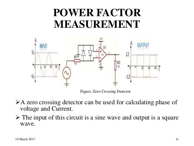
Zero crossing detection is often used in power control circuits. Power factor can be calculated using an oscilloscope, by each waveform is fed into a zero crossing detector (sometimes known. * there are also optoisolators with crossed input leds, which i could use without the diode bridge i assume. The zero crossing detector circuit find the time when the voltage cross the 0 volt as the initial reference therefore, measuring such values as current, voltage, frequency and power factor of the system is. A zero crossing detector circuit is mainly used for protecting electronic devices from switch on surges by ensuring that during power switch on the mains phase always enters' the circuit at its first zero crossing point.
Automatic Power Factor Correction from image.slidesharecdn.com Zero crosssing detector is a form of comparator that can detect zero crossing of ac input signal. Zero cross detection is a method which can enable us to. Voltage transformer and current transformer is used in. My project is to make power factor meter, my approach is to find out the zero crossing of both current and voltage, find out the time difference and then calculate the angle. Start date mar 29, 2004. Figure 3 results for a prototype circuit correlate well with the simulation. This implementation uses two optoisolators as shown in fig. Here is my preliminary circuit design for the pf measurement.
For synchronizing for firing thyristor based power.
Zero crossing detectors can have two types of output. Zero crossing detector for ac power control simulation in multisim. The zero crossing technique many years was widely used even in an analog electronics for ultrasonic measurements and later was well known in the numerical implementations. Here is my preliminary circuit design for the pf measurement. Im planning to build a power factor meter using the phase difference of the zero crossing of the voltage current zero crossing detector. I can measure current and voltage as only positive waves from 0 to 5v max 2. My project is to make power factor meter, my approach is to find out the zero crossing of both current and voltage, find out the time difference and then calculate the angle. For synchronizing for firing thyristor based power. This signal is not accessible by the block diagram. I'm trying to do a power factor measurement for academic work. The problem i have is what let's asume 1. Power factor measurement using microcontroller in proteus. Zero crossing detectors and comparators.
I'm measuring phase displacement between. Cost effective power factor measurement using microcontroller atmega8. * there are also optoisolators with crossed input leds, which i could use without the diode bridge i assume. Power factor measurement using microcontroller in proteus. The circuit charges capacitor c1 upto the limit that 22v zener diode accurately measure thepulse timing relative to the input zerocrossing.
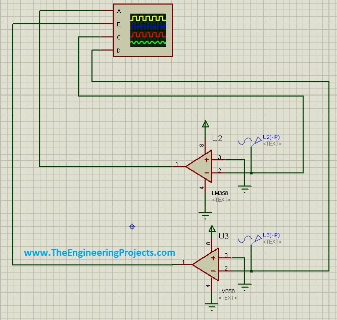
Power Factor Measurement Using Microcontroller The Engineering Projects from www.theengineeringprojects.com I will post it on arduino as well quite soon and may be on pic microcontroller as well. Here is my preliminary circuit design for the pf measurement. Where to use zero crossing detection? When the switch on dp4 is closed a low is detected and the program connects interrupt 0 turning on a interrupt service routine acon. I can measure the power factor (cos phi) by comparing the zero point crossing of voltage and current. Figure 3 results for a prototype circuit correlate well with the simulation. I need a zero crossing detector for a project i'm working on, and came across this design mentioned here on eevblog. The implementation used in this design identifies two points on the sine wave:
Voltage transformer and current transformer is used in.